
Guide 18 · Fastener Reference Guide
U-Bolt Dimension Chart
Round steel U-bolts for pipe supports, 15–600 NB — BG180 (not to grip) and BG181 (to grip) pattern dimensions.
A U-bolt is specified by two things: the nominal bore of the pipe it wraps, and whether it is meant to grip. The two patterns in this chart look identical on a shelf, and they do different jobs.
Not to grip vs to grip
- BG180 (not to grip) — sized with clearance around the pipe. The pipe can move axially through the support, which is what you want on long runs that expand and contract with temperature. The U-bolt locates the pipe; it does not clamp it.
- BG181 (to grip) — sized snug to the pipe outside diameter. Tightened down, it clamps the pipe and resists axial movement, suiting anchor points and short runs where the pipe must stay put.
Compare the N dimension across the two tables for any size and the difference is obvious — the not-to-grip pattern runs wider for the same pipe.
Reading the dimensions
Sizes are listed by nominal pipe bore (NB) with the matching pipe outside diameter. A is the bolt (rod) diameter, N the width across the legs, M the inside length, K the thread length, and S max. the maximum support thickness the threads can accommodate. All dimensions are millimetres; both patterns are carbon steel and come with four nuts.
If the run is insulated, remember the U-bolt wraps the pipe itself, not the lagging — talk to us about saddles and lined clamps where the insulation must stay unbroken.
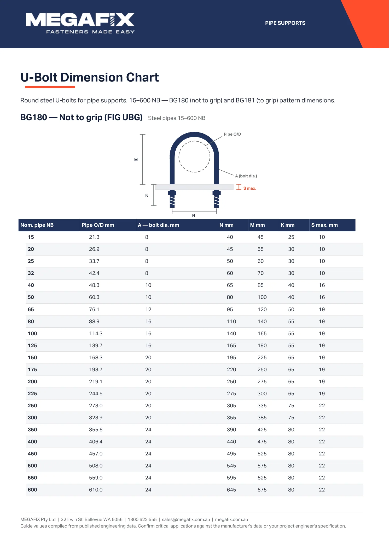

Text version — searchable and screen-reader friendly
BG180 — Not to grip (FIG UBG) Steel pipes 15–600 NB
| Nom. pipe NB | Pipe O/D mm | A — bolt dia. mm | N mm | M mm | K mm | S max. mm |
|---|---|---|---|---|---|---|
| 15 | 21.3 | 8 | 40 | 45 | 25 | 10 |
| 20 | 26.9 | 8 | 45 | 55 | 30 | 10 |
| 25 | 33.7 | 8 | 50 | 60 | 30 | 10 |
| 32 | 42.4 | 8 | 60 | 70 | 30 | 10 |
| 40 | 48.3 | 10 | 65 | 85 | 40 | 16 |
| 50 | 60.3 | 10 | 80 | 100 | 40 | 16 |
| 65 | 76.1 | 12 | 95 | 120 | 50 | 19 |
| 80 | 88.9 | 16 | 110 | 140 | 55 | 19 |
| 100 | 114.3 | 16 | 140 | 165 | 55 | 19 |
| 125 | 139.7 | 16 | 165 | 190 | 55 | 19 |
| 150 | 168.3 | 20 | 195 | 225 | 65 | 19 |
| 175 | 193.7 | 20 | 220 | 250 | 65 | 19 |
| 200 | 219.1 | 20 | 250 | 275 | 65 | 19 |
| 225 | 244.5 | 20 | 275 | 300 | 65 | 19 |
| 250 | 273.0 | 20 | 305 | 335 | 75 | 22 |
| 300 | 323.9 | 20 | 355 | 385 | 75 | 22 |
| 350 | 355.6 | 24 | 390 | 425 | 80 | 22 |
| 400 | 406.4 | 24 | 440 | 475 | 80 | 22 |
| 450 | 457.0 | 24 | 495 | 525 | 80 | 22 |
| 500 | 508.0 | 24 | 545 | 575 | 80 | 22 |
| 550 | 559.0 | 24 | 595 | 625 | 80 | 22 |
| 600 | 610.0 | 24 | 645 | 675 | 80 | 22 |
BG181 — To grip (FIG UBC) Steel pipes 15–600 NB
| Nom. pipe NB | Pipe O/D mm | A — bolt dia. mm | N mm | M mm | K mm | S max. mm |
|---|---|---|---|---|---|---|
| 15 | 21.3 | 8 | 30 | 50 | 25 | 7 |
| 20 | 26.9 | 8 | 35 | 60 | 25 | 10 |
| 25 | 33.7 | 8 | 45 | 65 | 25 | 10 |
| 32 | 42.4 | 8 | 55 | 75 | 25 | 10 |
| 40 | 48.3 | 10 | 60 | 90 | 35 | 16 |
| 50 | 60.3 | 10 | 75 | 100 | 35 | 16 |
| 65 | 76.1 | 12 | 90 | 130 | 45 | 19 |
| 80 | 88.9 | 16 | 105 | 160 | 50 | 19 |
| 100 | 114.3 | 16 | 135 | 175 | 50 | 19 |
| 125 | 139.7 | 16 | 160 | 200 | 50 | 19 |
| 150 | 168.3 | 20 | 190 | 235 | 55 | 19 |
| 175 | 193.7 | 20 | 215 | 260 | 55 | 19 |
| 200 | 219.1 | 20 | 245 | 295 | 55 | 19 |
| 225 | 244.5 | 20 | 270 | 310 | 55 | 19 |
| 250 | 273.0 | 20 | 300 | 350 | 60 | 22 |
| 300 | 323.9 | 20 | 350 | 400 | 60 | 22 |
| 350 | 355.6 | 24 | 385 | 440 | 65 | 22 |
| 400 | 406.4 | 24 | 435 | 500 | 65 | 22 |
| 450 | 457.0 | 24 | 485 | 540 | 70 | 22 |
| 500 | 508.0 | 24 | 540 | 600 | 70 | 22 |
| 550 | 559.0 | 24 | 590 | 650 | 70 | 22 |
| 600 | 610.0 | 24 | 640 | 700 | 70 | 22 |
Reference dimensions compiled from published pipe-support data (BS 3974 pattern figures). Carbon steel, supplied with 4 nuts. Illustrations are diagrammatic — not to scale. Specify the figure and nominal pipe size when ordering.